122 GHz Transverter
Construction
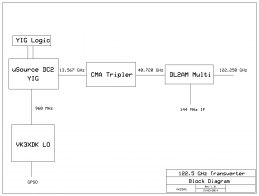
Here is the general plan. Based on 26 GHz Microsource MSS252 YIG Oscillators.
These oscillators take a 960 MHz reference to drive them so we will use a VK3XDK V1 LO which we can lock to a 10 MHz GPSO for the stability we will need.
This is then fed into a CMA tripler for our 40 GHz signal, then into a DL2AM housing with Kuhne PCB and MA4E1318 beam lead diode.
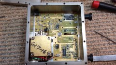
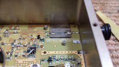
 The MSS252 has a tiny doubler just before it’s output, up on the top right in the picture.
  So that is removed which gives us our 13 GHz. I just nibbled some PCB out of an old LNB and trimmed it to the same size as the Maki doubler that was removed. This will also give me some room to “snow flake” the output to get the maximum signal out that I can get. Also LNBs are 12 GHz so I figured the PCB would be close enough.

